
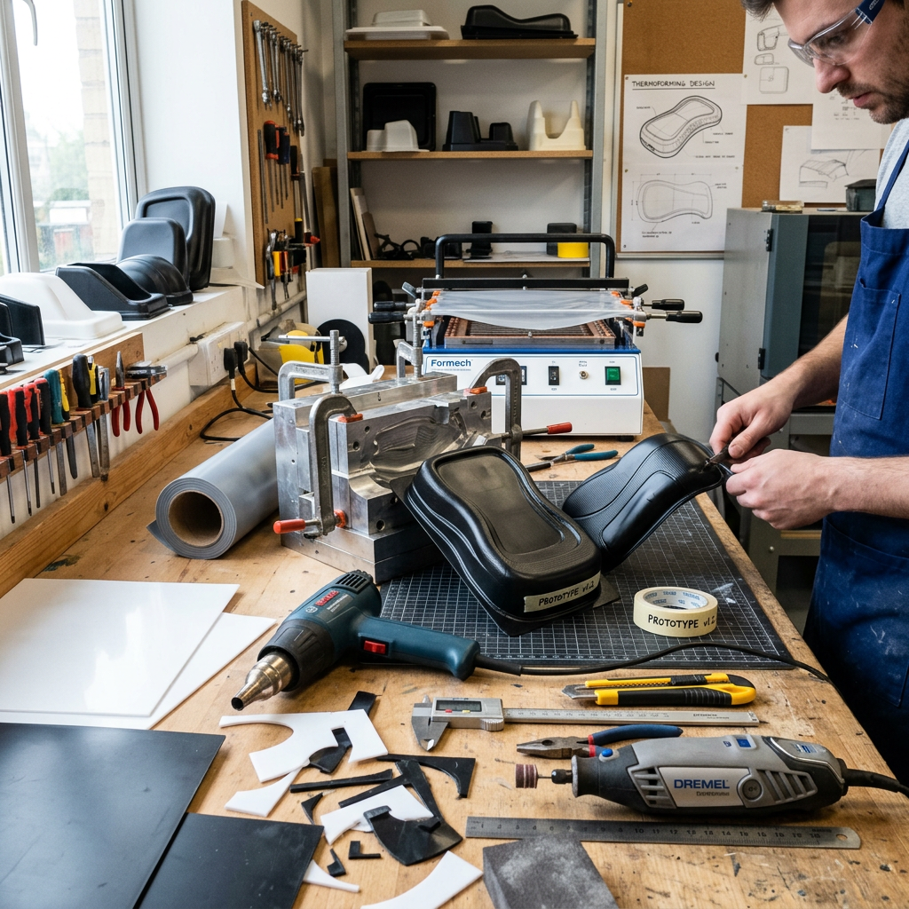
Key Takeaways
- Start with the part’s real performance requirements, not its appearance alone.
- Select materials based on impact, heat, chemical exposure, moisture, outdoor exposure, and finish requirements.
- Plan for wall-thickness changes due to sheet stretching during forming.
- Use draft, radii, accessible trim lines, and early prototypes to reduce production risk.
- Build inspection and end-of-life decisions into the design before production tooling is approved.
Why Design Decisions Matter Before Forming Begins
Thermoforming turns heated plastic sheet into a shaped component, then trims it into a usable part. A product may look simple, but its geometry, material, finish, mounting features, and production volume can all influence quality and cost. Teams planning a new cover, housing, tray, guard, or enclosure can visit this website to explore how custom thermoforming fits into a broader manufacturing plan.
The best results come from solving manufacturing questions before tooling begins. Early decisions affect strength, surface appearance, cycle time, trimming effort, scrap levels, and the ability to assemble the part with other components.
At its core, the basic thermoforming sequence involves heating sheet material, forming it against a mold, cooling it, and trimming the finished shape. Each step places limits on part geometry, so a practical design review should happen before drawings are released.
Define the Part’s Job First
Begin with a short performance brief. Identify what the part must do in real service, including the loads it carries, how often it is handled, and what happens if it flexes, gets scratched, or is impacted. This is more useful than choosing a resin based only on color or a previous project.
- Will the part experience impacts, vibration, bending, or repeated handling?
- Will it come into contact with oils, cleaners, moisture, food, or process fluids?
- Will it be used indoors, outdoors, or near heat-producing equipment?
- Does it need a textured, glossy, clear, colored, or paint-ready surface?
A protective equipment cover and a clear inspection guard may both be thermoformed, yet they have different requirements. The cover may need impact resistance and a durable texture, while the guard may need optical clarity, scratch resistance, and a shape that avoids visual distortion.
Match the Material to the Environment
Material selection should balance performance, forming behavior, availability, appearance, compliance requirements, and budget. ABS can be a practical choice for many durable housings, polycarbonate may suit high-impact or transparent applications, and other materials may be better when chemical resistance, heat performance, or weatherability is the priority.
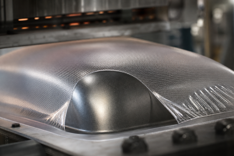
Review the actual production-grade technical data sheet rather than relying on the material family name. Two grades sold under the same broad resin category can differ in impact performance, ultraviolet resistance, flame rating, color options, and forming window. Request representative samples when appearance or environmental exposure matters.
Plan Wall Thickness and Material Distribution
The starting sheet thickness is not necessarily the final thickness throughout the part. As hot plastic stretches over a deep mold, material can become thinner at corners, sidewalls, and high-draw areas. The goal is not always a perfectly uniform thickness. It is a controlled thickness where the part carries loads, protects users, or supports assembly features.
- Identify deep draws, sharp transitions, and narrow corners.
- Set a minimum acceptable finished thickness for critical areas.
- Consider plug assists or other methods that improve material distribution.
- Test-first articles and measure the formed part, not just the CAD model.
Use Draft Angles and Generous Radii
Draft is the taper that helps a formed part release from the tool. An insufficient draft can cause sticking, scuffing, difficult ejection, and inconsistent surfaces. Tight corners can also concentrate stretching and reduce wall thickness. Add a draft in the direction the part leaves the tool, and use generous inside and outside radii wherever the design allows.
A housing with rounded corners often forms more evenly than a box-shaped housing with the same outside dimensions. Smooth transitions around openings, flanges, and mounting areas also help reduce stress concentrations and make trimming more predictable.
Choose the Right Forming Method
Process selection should reflect the shape, required detail, surface expectations, order quantity, and material behavior.
- Vacuum forming often works well for broad covers, trays, and parts where speed and economical tooling matter.
- Pressure forming can provide sharper definition and more refined surface detail.
- Mechanical forming may help control selected shapes through direct contact with the tool.
- Twin-sheet forming can create hollow or enclosed structures by joining two formed sheets.
Prototype Before Final Tooling
Prototypes should answer specific questions. One prototype may confirm fit with a mating assembly, while another may evaluate material flow, surface texture, trim location, or fastener access. Use prototypes to check that the part can release from the tool and that seals, inserts, drilled holes, and mounting hardware align as intended.
Document every change between the prototype and production design. A change that appears minor in CAD can alter draft, trimming access, thickness distribution, or cosmetic quality once the part is formed.
Add Trim Lines, Openings, and Mounting Features Carefully
Trimming, routing, drilling, bonding, and fastening are part of the design process, not afterthoughts. Place trim lines where they can be reached consistently. Keep holes away from thin edges and tight corners, provide flat land for seals or fasteners, and dimension openings from clear datums.
Drawing Review Checklist
- Are trim tolerances and critical dimensions clearly identified?
- Can operators inspect openings after trimming?
- Are mounting points strong enough for repeated use?
- Are cosmetic zones separated from areas that will be cut or machined?
Build Quality Checks into the Design
Define critical dimensions, cosmetic zones, and functional zones before production. Decide whether the team will use gauges, templates, scanners, or coordinate measurement. Common concerns include webbing, thin corners, warping, uneven color, poor detail definition, and trim variation. Preventing these issues is easier when the part design, tooling, material, and process settings are reviewed together.
Include Circular Design Choices from the Start
Lower waste begins with practical choices: avoid unnecessary thickness, reduce combinations of hard-to-separate materials, improve trim layouts, and consider whether worn components can be repaired or replaced. Teams can also plan how trim scrap and rejected parts will be handled, in line with broader recycling principles that emphasize keeping recoverable materials in useful circulation.
Review the Design with the Manufacturing Team
Designers, engineers, toolmakers, operators, and quality teams should review the project before production tooling is approved. Discuss service conditions, material choice, forming method, tooling maintenance, trim operations, packaging, inspection, and assembly requirements. Keep a simple decision record that explains why key features, tolerances, and materials were selected.
Common Questions About Thermoformed Part Design
What makes a thermoformed part strong?
Strength depends on material, formed wall thickness, corner geometry, ribs, support features, and the direction of applied loads. A thicker starting sheet alone may not solve a weak design.
How much draft is needed?
The right amount depends on material, tool texture, depth, surface finish, and forming method. Confirm the draft requirements with the toolmaker rather than applying a single general rule to every part.
Can thermoformed parts include holes and mounting points?
Yes. Features can be molded, trimmed, drilled, routed, or added through secondary assembly operations. Their placement should account for wall variation and edge strength.
Conclusion
Reliable thermoformed parts begin with clear requirements and early manufacturing input. When teams match material to the environment, control thickness in critical areas, plan draft-and-trim operations, test prototypes, and consider recovery options, they reduce late changes and produce parts that perform well in real use.
Discover more from The Cameron Journal
Subscribe to get the latest posts sent to your email.