
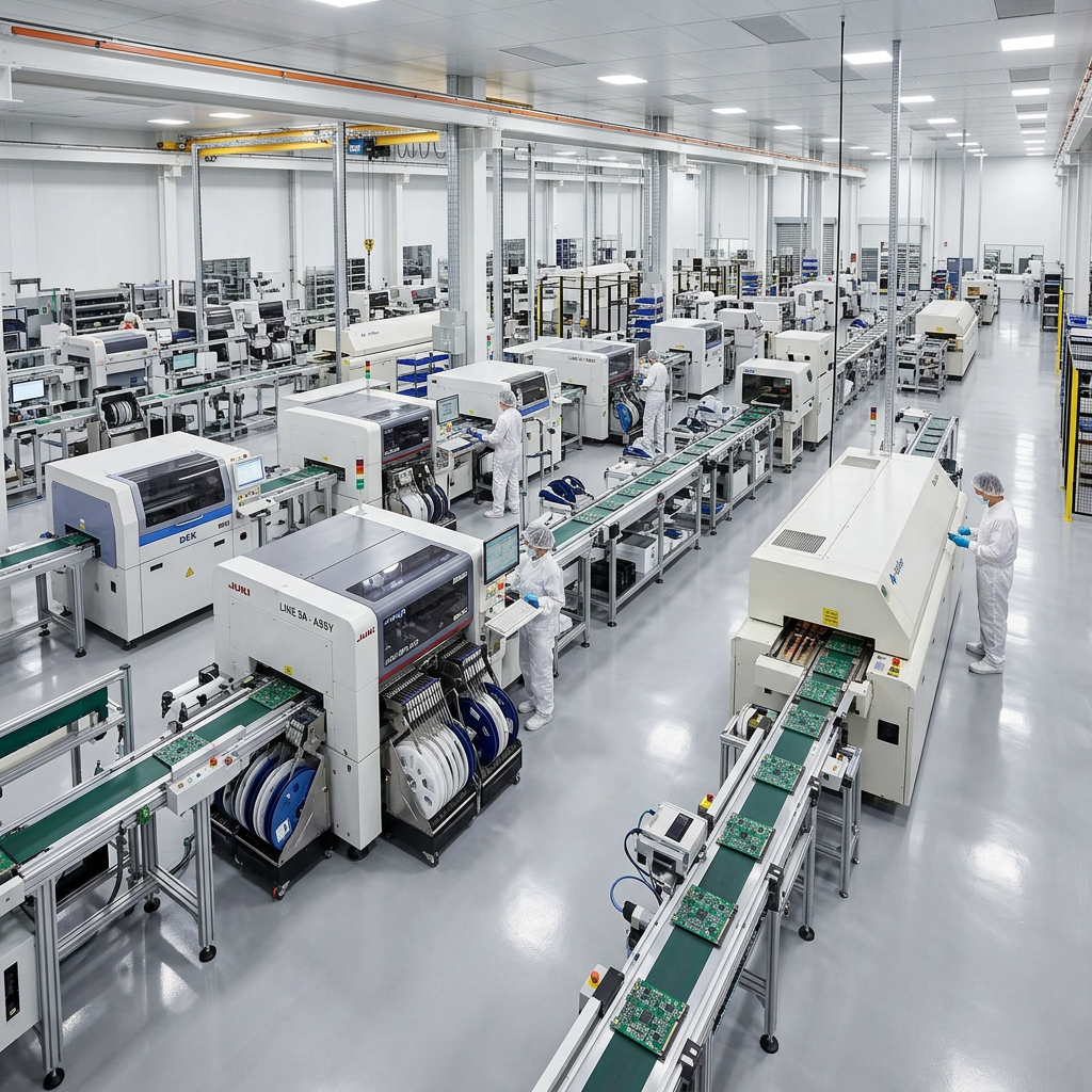
The first machine in a modern circuit board assembly line does not place a component. It prints solder paste. Before any chip reaches the board, a stencil printer pushes a gray mixture of metal particles and flux through openings in a thin metal sheet. This leaves a measured deposit on each pad.
Everything downstream depends on those deposits having the correct size, position, and shape. That is why printing receives so much attention in electronics manufacturing automation. In surface-mount technology (SMT), a widely used electronics assembly method, printing errors are often linked to a large share of production defects. A Siemens technical paper cites an estimate of about 60 percent, while reporting from Assembly Magazine similarly attributes more than half of SMT defects to printing problems. The precise share varies by process, but the practical lesson is consistent: print quality has an outsized effect on the finished board.
What a Stencil Printer Actually Does
The printing sequence is short, but it may repeat thousands of times per day. A bare board enters the machine, where it is clamped and supported from underneath. Cameras locate fiducials, the small reference marks printed on the board, and align the stencil with the pads.
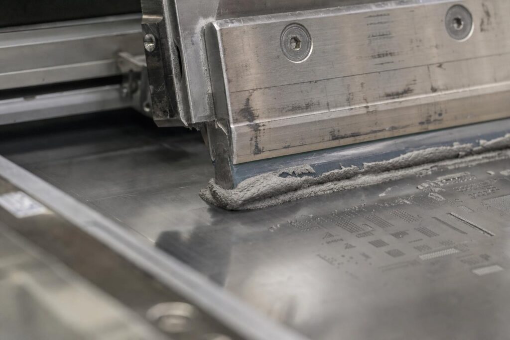
A squeegee blade then sweeps across the stencil. The moving blade rolls the paste along the surface and forces it into the stencil apertures. The stencil separates from the board in a controlled motion, leaving a deposit on each pad. The finished board exits, and the cycle begins again.
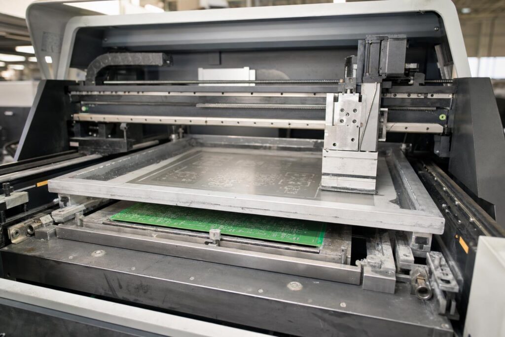
Between cycles, the machine may wipe the underside of the stencil to remove smeared paste. Some processes start with an interval of about 10 prints, but the correct setting depends on aperture size, paste behavior, board design, and inspection results.
Variables That Affect the Print Cycle
What looks like a single squeegee stroke depends on several connected settings. Squeegee pressure, speed, and blade angle affect how well the paste fills each opening. Separation speed influences whether deposits release cleanly or lose their shape. Too much pressure can also cause smearing or force paste under the stencil.
What a Good Print Looks Like
Two ratios help determine whether a stencil aperture can release paste reliably. Area ratio compares the open area of an aperture with the area of its interior walls. When this value is too low, paste is more likely to cling to the walls instead of transferring to the pad. IPC 7525 guidance recommends a minimum area ratio of 0.66.
Aspect ratio compares aperture width with stencil thickness. It is especially relevant to narrow openings and step stencils, where foil thickness varies across the sheet. IPC guidance for step-stencil designs pairs an area ratio of at least 0.66 with an aspect ratio above 1.5 to support complete release.
In practice, smaller components often require thinner foil and smooth aperture walls. Process engineers also monitor transfer efficiency, which is the percentage of the aperture’s intended paste volume that reaches the pad. Consistent transfer efficiency is usually more informative than a single acceptable print.
Why Early Inspection Controls Cost
Solder paste inspection (SPI) is usually performed by a 3D system that measures deposit height, area, position, and volume. It identifies missing paste, excessive paste, bridging, and alignment problems before components are placed.
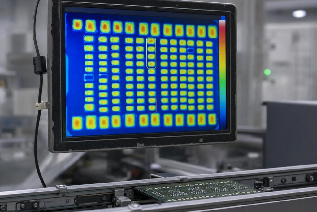
This timing matters because defects become harder to correct as the board moves through the line. At the paste stage, an affected board can often be cleaned and printed again. After placement or reflow, correction may require component removal, manual rework, or scrapping the board, which is why inspection coverage should be specified against your actual operational requirements rather than added later. If the problem reaches the field, it can also create warranty and reliability costs.
How Modern Printers Report Precision
Printer datasheets often describe accuracy in micrometers, but the smallest number is not always the most useful one. A specification should also include a Cpk value or sigma level. These measures indicate how consistently the process stays within a stated tolerance.
- ASMPT’s DEK TQ platform specifies wet-print accuracy of up to plus or minus 17 micrometers at 2 Cpk, with a five-second core cycle time.
- Panasonic’s SPG2 lists printing accuracy of plus or minus 15 micrometers at 2 Cp and 6 sigma, along with repeatability of plus or minus 4 micrometers at 2 Cpk and 6 sigma.
These figures are not direct equivalents. Machine alignment repeatability excludes some real-world variables, while full-process or wet-print figures include more of the actual printing cycle. Cycle-time definitions may also exclude board transfer, cleaning, or the print stroke. Buyers should compare the test conditions behind each number rather than ranking machines by the smallest published tolerance.
How to Compare Equipment
If SPI is part of the line, ask how the printer receives and uses inspection data. A claimed closed-loop connection should have clear rules for when settings change, how adjustments are recorded, and when an operator must intervene. It is also worth checking cleaning options, board-support tooling, maximum board dimensions, stencil compatibility, and local service coverage.
When comparing suppliers, build a shortlist that covers printers, board handling, inspection compatibility, and stencil storage rather than evaluating one machine in isolation. Requesting a print trial with representative boards can reveal issues that do not appear in a datasheet. Reviewing an SMT stencil printer from a full-line equipment provider may simplify compatibility checks, but it should still be compared with other suitable systems, support options, and total operating costs.
FAQ
These questions cover several practical issues that arise when planning or reviewing a stencil-printing process.
What is area ratio, and why does 0.66 come up so often?
Area ratio compares an aperture’s open area with the area of its interior walls. IPC 7525 guidance recommends a minimum of 0.66 because paste becomes less likely to release cleanly as the ratio falls below that level.
Do I need solder paste inspection?
It depends on production volume, board complexity, and risk tolerance. SPI is especially useful for fine-pitch components, high-value boards, and processes that need traceability. It catches paste defects before placement, when cleaning and reprinting are still practical.
The First Step Is Often the Easiest Place to Fix a Defect
Stencil printing may receive less attention than component placement or reflow, but it has a major influence on board quality. A stable process depends on suitable stencil design, controlled paste conditions, firm board support, consistent machine settings, and timely inspection. Understanding the print cycle and the limits of vendor specifications makes it easier to evaluate both individual printers and the wider assembly line.
Discover more from The Cameron Journal
Subscribe to get the latest posts sent to your email.